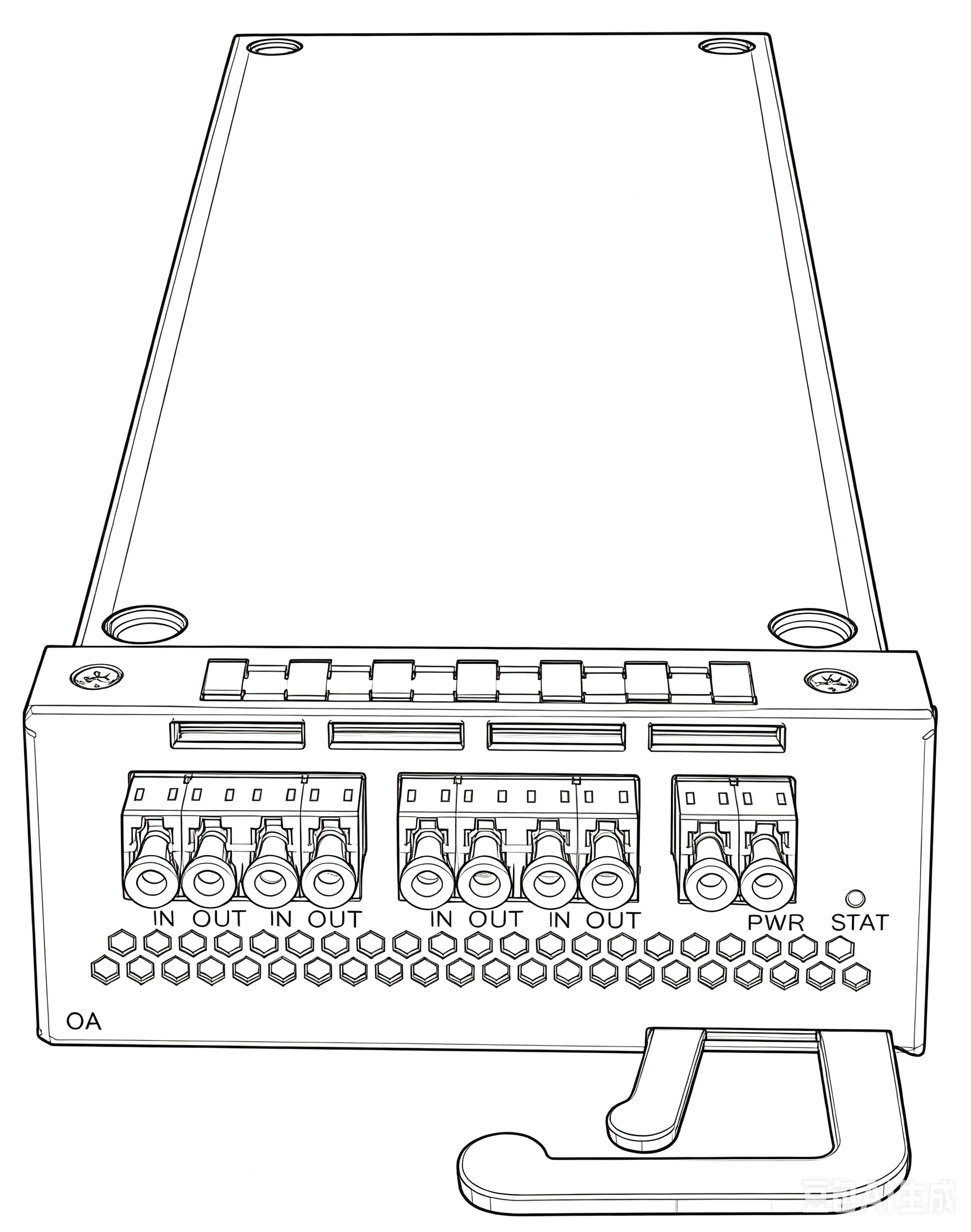
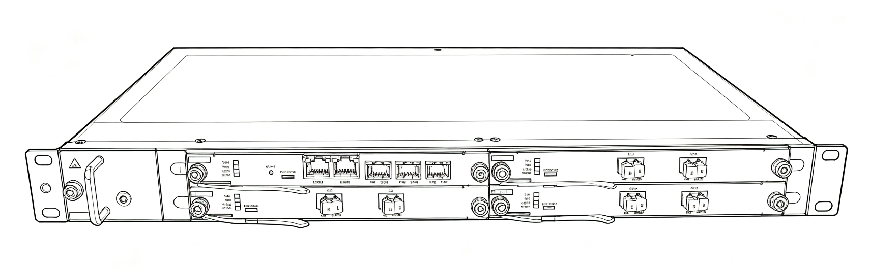
The Power Engine of DWDM Systems: High-Gain, Low-Noise EDFAs and Distributed Raman Amplifiers (RFA)
Purpose-built for DWDM backbone transmission and DCI interconnects. OTSLink delivers a complete portfolio of optical amplifier solutions, covering C+L band RFAs, +21.5dBm high-power Boosters, and dual-mode EDFAs. Every product passes full-band gain, noise, and high-temperature burn-in testing, giving your optical transport system exceptional margin and long-term stability.
System-Level Protection and Power Boosting: How to Choose?
Solution Type Distributed Raman Amplifier (RFA) Erbium-Doped Fiber Amplifier (EDFA) Core Role The “lifesaver” for the system noise floor (OSNR Booster) The “power engine” against span loss (Loss Compensator) Operating Principle Uses the transmission fiber itself as the gain medium to achieve distributed amplification. Uses erbium-doped fiber (EDF) to compensate signal attenuation in a lumped configuration. Typical Applications Ultra-long-haul transmission / weak-signal uplift
Compensates loss over long spans, lifts system OSNR by 3-5dB, and supports the C+L band. Transmit side / receive side / inline repeater
Line-side power boosting (Booster) and weak-signal amplification at the receiver (Pre-Amp). Key Advantages Extremely low noise figure, maximizing transmission distance. High gain and high output power (+21.5dBm), with gain flattening control (GFF).
Key Physical Criteria for Optical Amplifier Selection
Pain point: Excessive noise squeezes the OSNR margin of your system.
Selection advice: For long spans or receive-side amplification (Pre-Amp), an ultra-low-noise EDFA is a must; for extreme distances, prefer an RFA (Raman amplifier) working together with an EDFA.
Pain point: Excess power triggers fiber nonlinear effects, while insufficient power leaves the signal-to-noise ratio short.
Selection advice: A high-power Booster such as the OTS-OA-HP (+21.5dBm) is recommended at the transmit side. Pay equal attention to gain flattening control (GFF) and gain clamping, so that adding or removing a single channel does not shift channel power.
Pain point: Link loss fluctuates heavily and fixed gain cannot keep up.
Selection advice: Choose an EDFA with variable gain. Our OTS-OA-HP even integrates the OSC (optical supervisory channel), dramatically simplifying the deployment and commissioning of DCI equipment.
Eliminate Link Design Risk and Keep the Optical Layer Absolutely Secure
Customer Concerns OTSLink Solutions “Worried that link loss estimates are inaccurate and margins fall short after go-live” Full link budget simulation: During the pre-sales stage we provide a detailed OSNR and power budget report based on your fiber type, span loss, and amplifier model, with ample margin reserved for aging and maintenance. “After multiplexing many channels, channel power becomes unbalanced and links drop easily” Built-in gain flattening control (GFF): Our EDFAs/RFAs support dynamic gain equalization, effectively suppressing channel power drift and keeping C/L-band multi-channel systems absolutely stable. “What about aging degradation after years of continuous operation?” Rigorous high-temperature aging tests: Every optical amplifier we ship passes full-band gain, noise, and high-temperature aging tests, holding factory specifications even in extreme environments.
Typical Use Cases and Recommended Configurations
Short-Reach Metro DCI Interconnects
Recommended configuration: OTS-OA-HP (Booster/Pre-Amp dual mode)
Value: The +21.5dBm high-power output offsets fiber attenuation, while the integrated OSC removes the hassle of deploying a separate supervisory channel — plug and play, with drastically shorter delivery cycles.
Ultra-Long-Haul Backbone and Inter-Regional Trunk Networks
Recommended configuration: OTS-RFA (distributed Raman amplification) + OTS-EDFA
Value: The RFA amplifies the signal within the fiber ahead of time, significantly lowering the noise figure; combined with a high-gain EDFA, span reach extends dramatically and repeater station costs shrink.
Power Balancing at Metro DWDM Nodes
Recommended configuration: OTS-EDFA (standard erbium-doped fiber amplifier)
Value: Acting as the “power engine” of the system, it compensates the loss of mux/demux devices and fiber spans, supports C+L band expansion, and keeps service upgrades smooth.
Sample Trials & Worry-Free Support
Optical-Layer Performance: Let the Data Speak
Optical amplifiers are the cornerstone of the physical layer. OTSLink supports rigorous verification of sample specifications:
Factory test reports provided: Each sample ships with measured reports covering gain flatness, noise figure (NF), saturated output power, and other key parameters.
Link budget support: Professional optical link simulation is provided free of charge, ensuring that every amplifier you purchase precisely matches your live network.
Customized parameter configuration: Gain curves and gain-clamping ranges can be tailored to your specific transmission requirements.